
6.2. Frequency filters
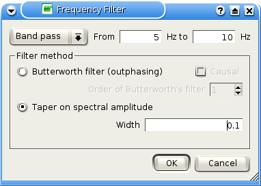
Figure 1: frequency filter paramters.
Four types of filters are available:
- Low pass: remove all frequency components above a frequency threshold (F2);
- High pass: remove all frequency components below a frequency threshold (F1);
- Band pass: remove all frequency components outside an interval [ F1, F2 ] ;
- Band reject: remove all frequency components inside an interval [ F1, F2 ] .
Two methods for filtering signals are implemented in geopsy.
Butterworth
Time Domain
Butterworth: this is a causal filter of adjustable order. The lowest order is the best (shortest) in the time domain, and the higher orders being better in the frequency domain. More information about such filters can be found for instance at sepwww.stanford.edu. Causality is an option of the filter. Causal filters are outphasing and vice-versa.
Spectral amplitude taper
Frequency Domain

Figure 2: filter function in frequency domain.
This filter does not alter the phase of the signals but it is not causal. The width of the transition is specified in the parameters (number between 0 and 1). A cosine function is used in the transition ranges.
The transition range is defined from the width and the corner frequencies F1 and F2. In figure 2, the spectrum of a delta-like function (uniform spectum) as been taken as an example. The spectum is filtered with the four types of filters. The light coloured lines around the main one are located at Fi*(1-width) and Fi*(1+width), i being 1 (red) or 2 (blue).
The specified frequencies are the limits above or below which the energy of the filtered signals is null. For instance, in the case of a band reject filter calculated between 0.5 and 3 Hz, there will absolutely no energy between 0.5 and 3 Hz.
